Privacy statement: Your privacy is very important to Us. Our company promises not to disclose your personal information to any external company with out your explicit permission.
In the 4G LTE system, since the antenna introduces MIMO technology, a well-known term “antenna port” in the daily work of network optimization is often mentioned, then what is the use of this antenna port or what is the original intention of the design? Consider it? Don't worry, listen to Xiao Bian slowly.
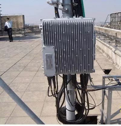
In the 23G system, there is no concept of an antenna port, and the concept of the channel is often mentioned. For example, one of the most proud technologies of the 3G TD-SCDMA system is the 8-channel antenna design. The channel refers to the internal physical division of the physical radio unit (RRU). Each channel independently carries a radio signal. Therefore, eight independent physical cables are also needed to feed the antenna unit. (The current polarized antenna looks from the outside At first, there are 4 antennas, but 8 radio frequencies are still physically available).

Figure 1 8-channel antenna and RRU
The antenna port introduced in 4G LTE is a logical concept. It is a different concept from the channel just mentioned, so it can be generally called by the name of the antenna logical port. The 3GPP protocol 36.211 defines the antenna logical port like this:
The channel environment experienced by different signals transmitted by the same antenna port is the same, and each antenna port corresponds to a resource grid. There is a strict correspondence between antenna ports and physical channels or signals.
I believe that some people who eat melon after reading this abstract definition are as confused as Xiao Bian’s first saw this sentence. In fact, this statement expresses the following two layers of deep meanings for the concept of an antenna logical port:
1. Although the antenna logic port is configured at the transmitter, its essential meaning is that the auxiliary receiver performs demodulation. The antenna logic port is an air interface-based identifier of the physical channel or physical signal, and the same antenna logic port channel environment. Like the change, the receiver can perform channel estimation accordingly to demodulate the transmission signal;
2. The receiver needs different concurrent decoding mechanisms for concurrent receiving and decoding of different logical ports.
In addition, although the antenna logical port is a division mechanism for logically different transmission signals, it has a corresponding relationship with the concept of antenna channels at the physical level. For example, if the antenna needs to be divided into logical ports, corresponding physical channel divisions are necessary. As a basic capability support, for example, two antenna logical ports correspond to at least two antenna physical channels, and of course, can also correspond to a channel with an integer multiple of 2, for example, 4 channels or 8 channels, so the 4T2R antenna in a LTE system is often encountered. Or the 4T4R antenna refers to an antenna physical channel, and the 4T2R antenna can be logically divided into 1, 2, and 4 logical ports in the downlink, but one physical channel cannot distinguish between two logical ports, so the antenna logical port and the physical Although the channels are two different concepts, they have a dialectical relationship.
In order to better understand the concept of antenna logical ports, we will study a small example together. The following is a description of the logical ports of the antenna belonging to the PSS/SSS physical channel in 3GPP 36.211:
The UE shall not assume that the primary synchronization signal is transmitted on the same antenna port as any of the downlink reference signals. The UE shall not assume that any transmission instance of the primary synchronization signal is transmitted on the same antenna port, or ports, Used for any other transmission instance of the primary synchronization signal.
This description shows two meanings.
1. The antenna logic port of the PSS/SSS is different from the antenna logical port of the downlink reference signal (for example, CRS), and the terminal should not be able to simultaneously decode the PSS/SSS when decoding the CRS antenna pattern based on the antenna logical port, and vice versa;
2. The terminal should not decode different PSS/SSS at the same time.
The CRS antenna pattern based on different antenna logical ports is shown in Figure 2.

Figure 2 Cell reference signal pattern corresponding to the number of antenna logical ports 1, 2, and 4
The following figure characterizes the time-frequency location of the PSS/SSS physical signal in the FDD radio frame format.

Figure 3 Time-frequency domain location of PSS/SSS in FDD radio frame format
The 4G LTE protocol does not clearly define the specific antenna logical port number for PSS/SSS (the specific antenna logical port is divided into p=4000 for the synchronization signal and the PBCH block in the 5G NR), based on the above for the antenna logical port and the PSS/SSS and reference The knowledge of the signal logical port relationship can be known when the terminal implements downlink synchronization in the frequency domain by periodically decoding the PSS/SSS (generally considered to be after the DRX). In the time slot 0 or 10, it should not “see” to the FIG. 2 . CRS antenna pattern.
November 16, 2024
November 14, 2024
September 18, 2023
June 28, 2024
June 28, 2024
この仕入先にメール
November 16, 2024
November 14, 2024
September 18, 2023
June 28, 2024
June 28, 2024

Privacy statement: Your privacy is very important to Us. Our company promises not to disclose your personal information to any external company with out your explicit permission.

Fill in more information so that we can get in touch with you faster
Privacy statement: Your privacy is very important to Us. Our company promises not to disclose your personal information to any external company with out your explicit permission.