![]()
6.3V220UF Volume: 5X8 own factory direct sales - solid capacitor - patch aluminum
![]()
Murata muRata winding inductance original authentic assured purchase
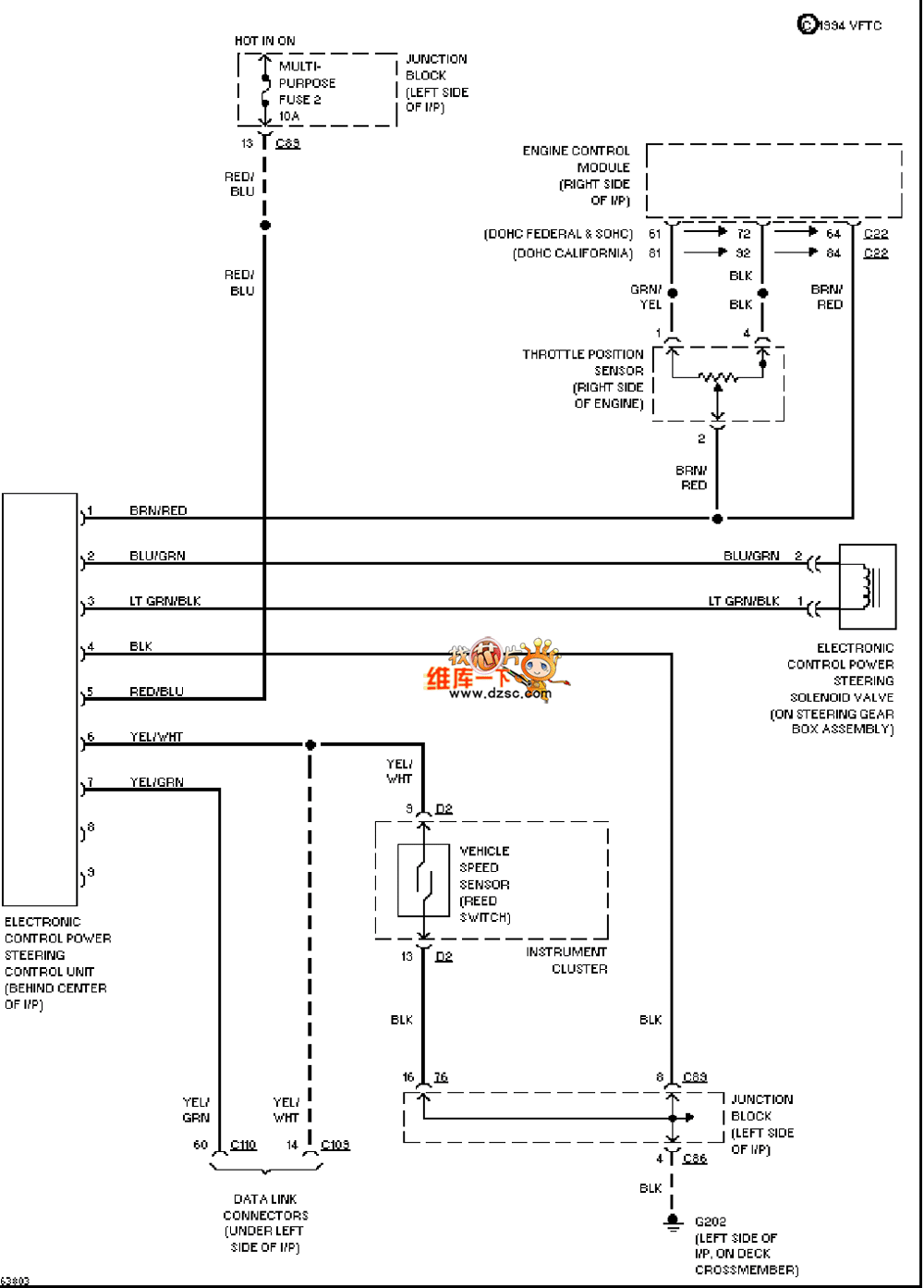
The Mazda 94DIAMANTE electric antenna circuit is shown below:

Welcome to reprint, information source Huaqiang Electronic Network ()
Circuit diagram layout:
Usually, the circuit diagram will be divided into sections according to the system or function to show the connection and relationship of each part more clearly.
The power circuit, control circuit, signal circuit, etc. may be shown separately to understand the overall working principle of the antenna system.
Power circuit:
Show how the electric antenna draws power from the vehicle power system (such as the battery).
May include protection components such as fuses and relays to ensure the safe operation of the circuit.
Control circuit:
Show the control logic of the electric antenna, such as receiving control signals through the body control module (BCM) or other control unit.
The control circuit may also include inputs such as switch signals and sensor signals, and output signals that drive the movement of the electric antenna.
Signal circuit:
If the electric antenna has signal reception or transmission functions (such as for vehicle communication or navigation), the circuit diagram will show the transmission path of these signals.
May include the connection between the antenna and the radio, navigation system, etc.
Grounding and shielding:
Show the ground connection of each part in the circuit diagram to ensure the stability and safety of the circuit.
May also include shielding measures to reduce the impact of electromagnetic interference on the performance of the antenna.
Wiring harnesses and connectors:
The circuit diagram will show the wiring harnesses, cables and connector types used in the electric antenna system in detail.
The wiring harnesses may be marked with colors, sizes and connector codes to facilitate correct identification and connection in actual operation.
Graphic symbols and codes:
Specific graphic symbols will be used in the circuit diagram to represent various electrical components and connection relationships.
The codes of connectors and components will be used to identify their type and location for quick location during repair and replacement.
Wifi Antenna, Router Antenna, Patch Antenna


