
Privacy statement: Your privacy is very important to Us. Our company promises not to disclose your personal information to any external company with out your explicit permission.
This article describes an easily fabricated 802.11b/g vertically-polarized omnidirectional antenna that is extremely rugged and has a gain of approximately 5-6 dBi.
Many sites have detailed instructions for making 2.4 GHz omnidirectional antennas. However, these antennas are quite complex to implement, and many small coaxial cables with very precise cuts are used. At the same time you must also know the data of the coaxial cable used, because most of the dimensions are based on this. Some modified coaxial omnidirectional antennas are made of brass rods and brass tubes, but they also require high-precision processes.
Not long ago, an 8-element coaxial cable antenna was made. Nearly 8dBi gain has been tested. The production took more than N hours, but the mechanical strength was not very satisfactory. So I wrapped a reinforced wooden strip around the coaxial cable antenna and put it into a 25mm wire duct. When a friend told me that someone bent a copper wire into a simple antenna, there was a gain of 6dBi and my curiosity was inspired.
This antenna has some advantages over a coaxial cable antenna, which reduces the difficulty of production and makes the antenna smaller and more robust. Although the gain of 6dBi is less than the 8-cell coaxial cable antenna, it can be improved by increasing the number of components. Every two units can increase the gain of 3dBi.
Required device:Required raw materials
. . About 300mm long, 2.5mm square copper wire
. . N type female connector
. . 250mm long, outside diameter 20mm light wire conduit
. . 2 end caps for 20mm wire conduit
Of course, assembling an antenna also requires:
. . 2 fixtures for 20mm wire conduits
or:
. . Metal stent
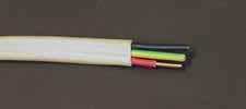
I used a scrap copper wire with a 2.5 mm square section. This copper wire is approximately 1.6mm in diameter and can be bent to the desired shape without any special tools.
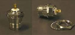
You also need an N-type female connector to connect the antenna to the wireless device. Other connectors (eg, TNC, SMA, etc.) can also be used, depending on the connector on your cable end. I use the following
A section of copper wire, which is bent at certain positions to form an antenna. The size of each part is very important, refer to the following picture

The bottom is 1/2 wavelength, the middle is 3/4 wavelength, and the top is slightly smaller than 3/4 wavelength in order to reduce the effect of capacitance.
The 802.11b standard uses the 2.412MHz to 2.484MHz frequency range. The 1/2 wavelength of the center frequency is 61mm, and the 3/4 wavelength is 91.5mm. These sizes appear to be the same as those sold outside.
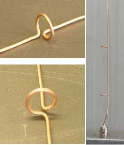
Starting from the bottom of the antenna, a piece of copper wire is welded on the N-type connector. Take the 1/2 wavelength from the top of the N connector and make the first ring.
Note that the ring should be misaligned with the copper line so that the copper line remains a straight line.
Then measure 3/4 wavelengths and make a second ring. Leave enough length at the top and cut the copper wire.
If you plan to use a 20mm diameter wire conduit, make sure the diameter of the ring is equal to or less than 15mm so that it fits into the wire conduit (16mm for the 20mm lightweight wire conduit).
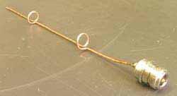
After a long period of time, the copper wire is not strong enough. The simplest method is to put an antenna on the antenna.
Note that the shell uses those substances that are easily penetrated by 2.4GHz, otherwise it will affect the performance of the antenna.
I used a light wire conduit with a diameter of 20mm and a length of 250mm with two small covers. Its inner diameter is 16mm, so that those rings are just right for this wire conduit.
If you want to be more relaxed, you can use a 25mm diameter light wire conduit.
Near the base of the wire, bend two small bends. In this way, when the antenna is placed in the conduit, it is ensured that those loops are located in the center above the N-type connector. Experiments have shown that these two small bends will not have any effect on the effect of the antenna.

When assembling the antenna, drill a small hole of the appropriate size into the cap on one end, pass the N-type connector through the hole, and screw the N-type connector on the cap with the nut and washer from the outside.
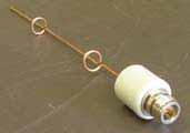
The antenna is fitted with a wire conduit and the cover at the other end is also covered.
If the antenna is used outdoors, the covers at both ends must be glued with a special wire conduit glue to ensure that the seal is protected from rain. Note that the antenna should be tested before glue water.
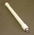
The wire conduit provides a robust housing for the antenna and can be installed outdoors if required. If it is installed outdoors, be sure to wrap the self-adhesive tape around the N-type connector to prevent moisture immersion. Plastic clips secure the antenna to a vertical wall. Because these clips are plastic, they do not interfere with the antenna, and all metal brackets affect the antenna's radiation.
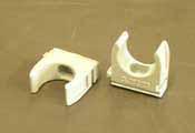
When the clip is installed in the place where the antenna is to be installed, the antenna can be easily attached to the clip and the antenna can be easily moved.
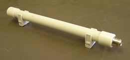
Another method of installation is to use a small piece of right angle galvanized steel to drill a suitable hole in the steel sheet. The N-joint is fixed to the steel sheet through that hole.
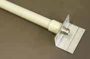
If you want to move the antenna freely, you don't need to fix it, but use it like a hand-held antenna.

When I use this scheme as the first antenna, like the ones sold outside, coil the copper wire to the center of the ring so that the copper wire maintains a straight line in the center of the ring.
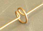
But then I did some research and found that it was wrong. When doing another antenna, it was made in accordance with each step described above.
Tests have shown that ring-biased antennas perform better than those with copper wires in the center of the ring.
January 17, 2025
January 11, 2025
September 18, 2023
June 28, 2024
June 28, 2024
December 10, 2024
この仕入先にメール
January 17, 2025
January 11, 2025
September 18, 2023
June 28, 2024
June 28, 2024
December 10, 2024

Privacy statement: Your privacy is very important to Us. Our company promises not to disclose your personal information to any external company with out your explicit permission.

Fill in more information so that we can get in touch with you faster
Privacy statement: Your privacy is very important to Us. Our company promises not to disclose your personal information to any external company with out your explicit permission.