Privacy statement: Your privacy is very important to Us. Our company promises not to disclose your personal information to any external company with out your explicit permission.
1 Introduction
With the rapid development of wireless communication technology, the application range of microwave communication technology communication is very wide. Microwave antennas are the most important part of microwave communication systems. Almost all the information that can be transmitted by electromagnetic waves depends on the transmission and exchange of microwave antennas. At the same time, microwave antennas can also radiate electromagnetic waves and other energy. The microwave antenna is the "gateway" of the transceiver equipment of the microwave communication system, and the performance of the antenna directly affects the operation of the entire system. Although there are many research results on microwave antenna optimization at present, most of them are considered from a single factor, and the optimization effect is not very ideal. This article looks for a more reasonable selection method by comprehensively considering multiple factors and optimizing the selection parameters of microwave antenna.
2 Research on factors that should be considered when selecting microwave antennas
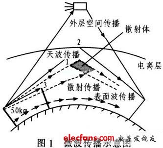
Figure 1 is a schematic diagram of microwave propagation. During the transmission process, microwave signals are affected by the refraction and diffraction of the atmosphere, sea surface, ground, tall buildings, and mountain peaks, resulting in signal fading and distortion, or even interruption. Therefore, to optimize the microwave transmission antenna, it is necessary to study the influencing factors of microwave transmission in accordance with the basic characteristics of microwave communication, and then optimize to reduce signal fading and distortion.

2.1 Ground terrain factors
In microwave communication systems, signal transmission mainly uses microwave line-of-sight propagation. The frequency of microwave communication is mostly in the range of 2 to 20 GHz. Different terrain conditions have different reflection coefficients and level losses. When radio waves are transmitted in free space, the energy per unit area will be reduced due to free diffusion. The reduced energy is called free space transmission loss. It is expressed by Ls and the unit is decibel (dB). The calculation formula is:

In the formula, f is the transmission frequency, GHz; d is the station distance, km.
It can be seen from equation (1) that during the propagation of microwaves, forests, buildings, hilltops, or ground obstacles will block some electromagnetic waves and increase losses. The smooth ground or water surface can reflect part of the signal to the receiving antenna. The addition of the reflected wave and the direct wave vector may cancel each other and cause additional loss. Ground reflection has an important effect on line-of-sight propagation, and it is one of the main causes of level fading. However, when there is a blade-shaped obstacle (or mountain peak) on the microwave transmission path, if the peak of the obstacle happens to fall on the connection between the receiving antenna and the transmitting antenna of two adjacent microwave stations, the microwave transmission will increase by 6 dB level attenuation; when the peak of the obstacle exceeds the connection, the level attenuation will increase faster. In practical applications, this situation should be avoided. The transmission characteristics can be modified by modifying the microwave transmission line or increasing the antenna. In order to better analyze the propagation characteristics of microwaves, the concept of Fresnel zone is used for analysis, then the radio wave from the wave source to the observation point can be considered to propagate through many Fresnel zones, and the combined field strength at the observation point E≈ E1 / 2 (E1 is the field strength of the first Fresnel zone), that is, as long as half of the first Fresnel zone is not blocked by terrain features. The field strength during free space propagation can be approximated. To know how high the barrier is to meet the propagation conditions, the radius F1 of the first Fresnel zone must be calculated in m, and the calculation method is:

In the formula, d refers to the distance between sending and receiving, km; λ is the wavelength, m.
It can be seen from equation (2) that in order to avoid additional losses, all obstacles must be outside the first Fresnel zone. When the height of the ground obstacle is constant, the longer the wavelength, the larger the cross-sectional area of the main channel for radio wave propagation, the smaller the relative shielding area, and the larger the field strength at the receiving point. Therefore, the lower the frequency, the more the diffraction ability Strong.
January 17, 2025
January 11, 2025
September 18, 2023
June 28, 2024
June 28, 2024
December 10, 2024
この仕入先にメール
January 17, 2025
January 11, 2025
September 18, 2023
June 28, 2024
June 28, 2024
December 10, 2024

Privacy statement: Your privacy is very important to Us. Our company promises not to disclose your personal information to any external company with out your explicit permission.

Fill in more information so that we can get in touch with you faster
Privacy statement: Your privacy is very important to Us. Our company promises not to disclose your personal information to any external company with out your explicit permission.